
1. Sarrera
The KELUSHI XQ-350 Wire Tracker is a versatile tool designed for telecommunication network line engineering, routine servicing, and computer network line maintenance. It assists in tracing wires, verifying LAN cable conditions, and performing continuity tests on various metal wire lines.
Paketearen edukia
Paketea irekitzean, egiaztatu honako elementu guztiak daudela:
- 1x Emitter Unit
- 1x Hargailu Unitatea
- 1x entzungailu
- 1x RJ11 Adapter Cable
- 1x Alligator Clip Adapter Cable
- 1x RJ45 Adapter Cable
- 1x Erabiltzailearen eskuliburua (dokumentu hau)
- 1x Toolkit/Carrying Case

Figure 1.1: KELUSHI XQ-350 Wire Tracker and included accessories.

Figure 1.2: The carrying case and a list of its contents, ensuring all components are accounted for.
2. Product Features and Functions
The XQ-350 Wire Tracker offers a range of functionalities to assist in network and telephone cable management:
- Wire Tracing: Locate telephone wires and LAN cables within electrical systems.
- LAN Cable Verification: Assess the condition of LAN cables, identifying open circuits, short circuits, and cross-connections.
- Jarraitasun proba: Perform basic continuity checks on cables.
- Bateria baxuaren adierazlea: Erabiltzaileari bateriaren maila baxua denean abisatzen dio.
- LED linterna integratua: Provides illumination in dark working environments.
- Cable Assignment Test: Specifically tests 2-wire (RJ11) and 4-wire (RJ45) telephone cables for open, short, and cross faults.
- Cable State Testing (2-wire): Detects DC line voltage, determines anode/cathode polarity, and identifies ringing signals.
- Target Wire Identification: Quickly find specific wires among bundles of telephone or network cables by comparing sound volume and signal indicator brightness.
- Ethernet Switch/Router Compatibility: Capable of finding wires connected to operating Ethernet switches, routers, or PC terminals.
3. Osagaien identifikazioa
3.1 Emitter Unit

3.1. irudia: Aurrealdea view of the Emitter unit with key components labeled.
The Emitter unit features:
- RJ11 ataka: For connecting telephone cables.
- RJ45 ataka: Sareko kableak konektatzeko.
- Wire Finding Indicator (STATUS): LEDs indicating the status during wire tracing.
- Function Switching Button: Cycles through different test modes.
- Funtzio hautatzaile etengailua: Toggles between SCAN, OFF, and TEST modes.
- Wire Sequence Indicator (1-8, G): LEDs that light up to show cable continuity and wiring sequence.
- Testing Indicator (VERIFY): Indicates the result of cable verification.
3.2 Hartzailearen Unitatea

3.2. irudia: Aurrealdea view of the Receiver unit with key components labeled.
The Receiver unit features:
- Zunda: Used to detect the signal emitted by the Emitter.
- Seinalearen adierazlea: Visual indication of signal strength.
- Inching Button (PUSH TO TEST): Activates the signal detection.
- PWR-VOL Switch: Power and volume control for the receiver.
- Entzungailuen Jack: For connecting the included earphone for clearer audio detection.
- Volume Adjuster: Audio irteerako maila kontrolatzen du.
- Spotlight Switch: Barneko LED linterna aktibatzen du.
- Wire Sequence Indicator (1-8, G): LEDs mirroring the Emitter's indicators during cable testing.
- RJ45 ataka: For connecting network cables during testing.
3.3. irudia: Xehetasuna views of the RJ45/RJ11 ports, probe, power switch, and speaker on the XQ-350 units.
4. Konfigurazioa
4.1 Bateriaren instalazioa
Both the Emitter and Receiver units require a 9V DC battery (not included) for operation.
- Locate the battery compartment cover on the back of each unit.
- Irristatu edo askatu estalkia konpartimentua irekitzeko.
- Konektatu 9V-ko bateria bat bateriaren kliparekin, polaritate zuzena ziurtatuz.
- Jarri bateria konpartimentuaren barruan eta itxi estalkia ondo itxita.

Figure 4.1: Open battery compartments of the Emitter and Receiver, showing where to insert the 9V laminated battery.
4.2 Konektatzeko kableak
Use the appropriate adapter cables (RJ45, RJ11, or alligator clips) to connect the Emitter to the cable you wish to test or trace. The Receiver is used to detect the signal or verify the cable status.
5. Funtzionamendu-argibideak
5.1 Wire Tracing (SCAN Mode)
This mode is used to locate a specific wire among a bundle of cables.
- Connect the Emitter to one end of the target cable using the appropriate adapter (RJ45, RJ11, or alligator clips).
- Set the Function Selector Switch on the Emitter to 'SCAN'. The 'STATUS' indicator will light up.
- Turn on the Receiver by adjusting the PWR-VOL switch. Adjust the volume to a comfortable level.
- Use the Receiver's probe to scan the cables at the other end or along the cable path.
- When the probe is near the target wire, the Receiver will emit an audible tone. The signal indicator LEDs will also light up.
- The target wire is identified by the loudest tone and brightest signal indicator.
- For clearer audio, connect the earphone to the Receiver's headset jack.
5.2 LAN Cable Testing (TEST Mode - RJ45)
This mode verifies the wiring sequence and identifies faults in RJ45 network cables.
- Connect one end of the RJ45 cable to the Emitter's RJ45 port and the other end to the Receiver's RJ45 port.
- Set the Function Selector Switch on the Emitter to 'TEST'.
- Observe the Wire Sequence Indicator LEDs (1-8, G) on both the Emitter and Receiver.
- Konexio arrunta: LEDs on both units will light up sequentially from 1 to 8, then G (ground), indicating a correct wiring sequence.
- Zirkuitu irekia: If a specific LED (e.g., '3') does not light up on either unit, it indicates an open circuit on that wire.
- Zirkuitu laburra: If two or more LEDs light up simultaneously or out of sequence, it indicates a short circuit between those wires.
- Cross-Connection: If the sequence of LEDs on the Receiver differs from the Emitter, it indicates a cross-connection.
5.3 Telephone Cable Testing (TEST Mode - RJ11)
This mode is used for 2-wire telephone cables to check continuity and state.
- Connect one end of the RJ11 cable to the Emitter's RJ11 port using the RJ11 adapter.
- For cable state testing, connect the other end of the RJ11 cable to the line you wish to test.
- Set the Function Selector Switch on the Emitter to 'TEST'.
- Line DC Detecting and Anode/Cathode Determination: The Emitter will indicate the presence of DC voltage and its polarity.
- Ringing Signal Detecting: The Emitter can detect if a ringing signal is present on the line.
- Open, Short, and Cross Testing: Similar to LAN cable testing, the LEDs will indicate faults.
5.4 LED linterna erabiltzea
The Receiver unit includes a built-in LED flashlight for working in dimly lit areas.
- Locate the Spotlight Switch on the side of the Receiver unit.
- Slide the switch to the 'ON' position to activate the flashlight.
- Slide the switch to the 'OFF' position when not in use to conserve battery life.
6. Mantentzea
6.1 Bateria ordezkatzea
When the low battery indicator illuminates or the unit's performance degrades, replace the 9V battery in both the Emitter and Receiver units as described in Section 4.1.
6.2 Garbiketa eta biltegiratzea
- Clean the units with a soft, dry cloth. Do not use abrasive cleaners or solvents.
- Gorde gailua leku fresko eta lehor batean, eguzki-argitik eta muturreko tenperaturetatik babestuta.
- Denbora luzez gordetzen baduzu, kendu bateriak isuriak eta gailua kaltetzea saihesteko.
7. Arazoak
7.1 Potentziarik gabe
- Ensure the 9V battery is correctly installed with proper polarity.
- Ordeztu bateria berri batekin.
- Check that the power switch (PWR-VOL on Receiver, Function Selector on Emitter) is in the 'ON' or 'SCAN'/'TEST' position.
7.2 No Signal During Wire Tracing
- Verify the Emitter is set to 'SCAN' mode.
- Ensure the Emitter is properly connected to the cable.
- Adjust the Receiver's volume to maximum.
- Confirm the Receiver's probe is in close proximity to the target cable.
- Check for excessive electromagnetic interference in the environment.
7.3 Incorrect Cable Test Results
- Ensure both ends of the cable are securely connected to the Emitter and Receiver.
- Verify the Emitter is set to 'TEST' mode.
- Egiaztatu kablea eta konektoreak kalte ikusgairik duten.
- Test with a known good cable to confirm the device is functioning correctly.
8. Zehaztapenak
The following table outlines the technical specifications for the KELUSHI XQ-350 Wire Tracker:

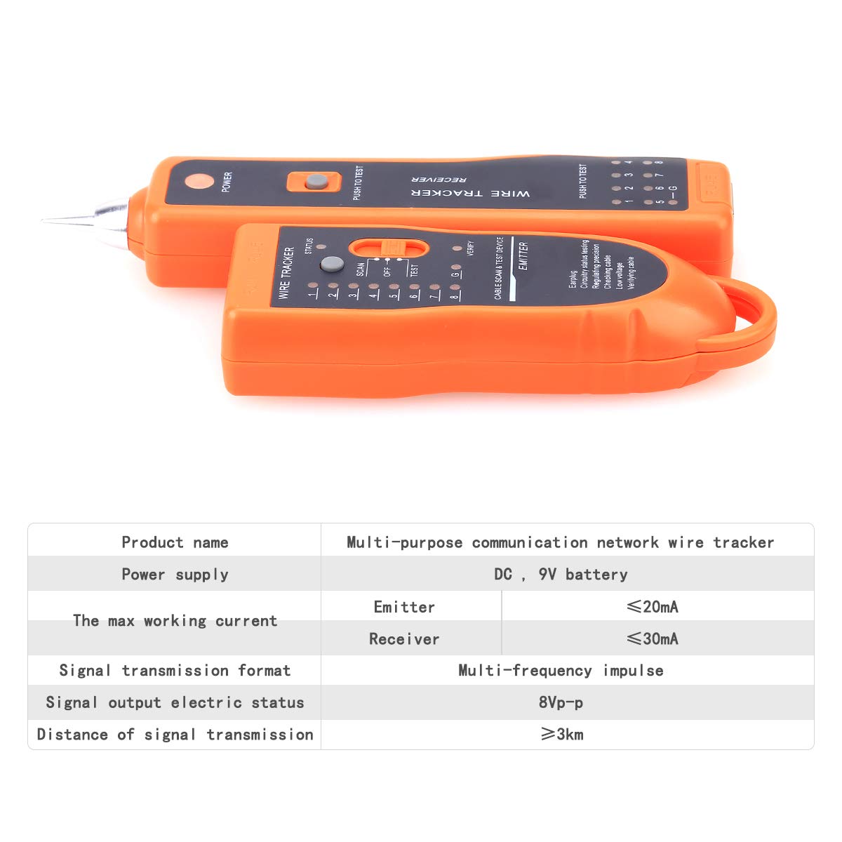
Figure 8.1: Visual representation of the KELUSHI XQ-350 Wire Tracker's key specifications.
| Parametroa | Balioa |
|---|---|
| Eredua | XQ-350 |
| Elikatze Hornidura | DC 9V bateria (ez dago barne) |
| Working Current (Emitter) | ≤10mA (Test mode) |
| Working Current (Receiver) | ≤30mA |
| Signal Transmission Format | Multiple frequency pulse |
| Signal Output Electric Status | 8VP-P |
| Distance of Signal Transmission | ≥3 km |
| Kolorea | Laranja |
| Materiala | ABS plastikoa |
| Igorlearen Dimentsioa | Gutxi gorabehera. 12.8 × 4.5 × 2.5 cm |
| Hartzailearen Dimentsioa | Gutxi gorabehera. 17.5 × 4 × 2.2 cm |
| Elementuaren pisua | 250 gramo |
9. Laguntza
For any questions or assistance regarding the KELUSHI XQ-350 Wire Tracker, please contact the manufacturer or seller. Refer to your purchase documentation for specific contact details.