REOLINK B10-2 Pack
REOLINK Junction Box B10 Instruction Manual
Model: B10-2 Pack
Sarrera
The REOLINK Junction Box B10 is designed to provide a secure and weather-resistant enclosure for the wiring connections of compatible REOLINK bullet cameras. Constructed from durable aluminum alloy, this junction box ensures a clean installation and protects cable connections from environmental elements, making it suitable for both indoor and outdoor applications.
This manual provides detailed instructions for the installation and proper use of your REOLINK Junction Box B10.
Produktuaren Ezaugarriak
- Materiala: Made of high-quality aluminum alloy for durability.
- Babesa: Diseinu iragazgaitza, barruko eta kanpoko erabilerarako egokia.
- Instalazioa: Designed for convenient and easy installation.
- Bateragarritasuna: Specifically designed for various REOLINK bullet cameras, including B400, RLC-510A, RLC-510WA, RLC-810A, RLC-811A, RLC-811WA, RLC-81MA, RLC-81PA, RLC-1210A, Duo 2 PoE, Duo 2 WiFi, and CX410.
- Paketearen edukia: Each pack includes two B10 Junction Boxes.
Paketearen edukia
Egiaztatu elementu guztiak zure paketean sartuta daudela:
- REOLINK Junction Box B10 x 2
- Mounting Screws and Wall Plugs (typically included with the junction box)
- Installation Template (if provided)
Bateragarritasuna
The REOLINK Junction Box B10 is compatible with the following REOLINK bullet camera models:
- B400
- RLC-510A
- RLC-510WA
- RLC-810A
- RLC-811A
- RLC-811WA
- RLC-81MA
- RLC-81PA
- RLC-1210A
- Duo 2 PoE
- Duo 2 WiFi
- CX410

Figure 1: Compatible REOLINK Camera Models
Konfigurazioa eta Instalazioa
Follow these steps to properly install the REOLINK Junction Box B10 with your compatible camera. Ensure power is disconnected from the camera before beginning installation.
Beharrezko tresnak (ez daude barne):
- Zulagailua
- Drill bit appropriate for wall plugs
- Bihurkin (Phillips burukoa gomendatzen da)
- Arkatza edo errotulagailua
Instalazio urratsak:
- Step 1: Prepare the Junction Box.
Open the junction box. If routing cables through the side, remove the appropriate knockout. If routing through the back, ensure the cable entry point is clear. Connect your camera's network cable (e.g., Ethernet) through the cable gland at the bottom of the junction box. Ensure the cable gland is tightened to provide a waterproof seal.

Figure 2: Installation Steps Overview
- Step 2: Mark Drilling Positions.
Place the junction box against the desired mounting surface. Use a pencil or marker to mark the positions for the mounting screws through the pre-drilled holes on the junction box. Ensure the box is level before marking.
- Step 3: Drill Holes and Insert Wall Plugs.
Drill holes at the marked positions. Insert the provided wall plugs into the drilled holes. For wooden surfaces, wall plugs may not be necessary.
- Step 4: Mount the Junction Box Base.
Align the junction box base with the drilled holes and secure it to the wall using the mounting screws. Ensure it is firmly attached.
- Step 5: Connect Camera Cables.
Inside the junction box, connect the camera's cables (e.g., Ethernet, power if applicable) to the appropriate connections. Neatly arrange excess cable within the box.
- Step 6: Attach Camera to Junction Box Cover.
Align the mounting holes on your REOLINK camera with the corresponding screw holes on the junction box cover. Secure the camera to the cover using the camera's mounting screws. The cover has multiple pre-drilled patterns (A1, B1, C1, D1, etc.) to accommodate various camera models. Refer to your camera's manual for its specific mounting pattern.

Figure 3: Junction Box Cover with Multiple Mounting Patterns
- Step 7: Secure the Cover to the Base.
Once the camera is attached to the cover and cables are managed, align the cover with the junction box base and secure it using the provided screws. Ensure a tight seal to maintain waterproof integrity.
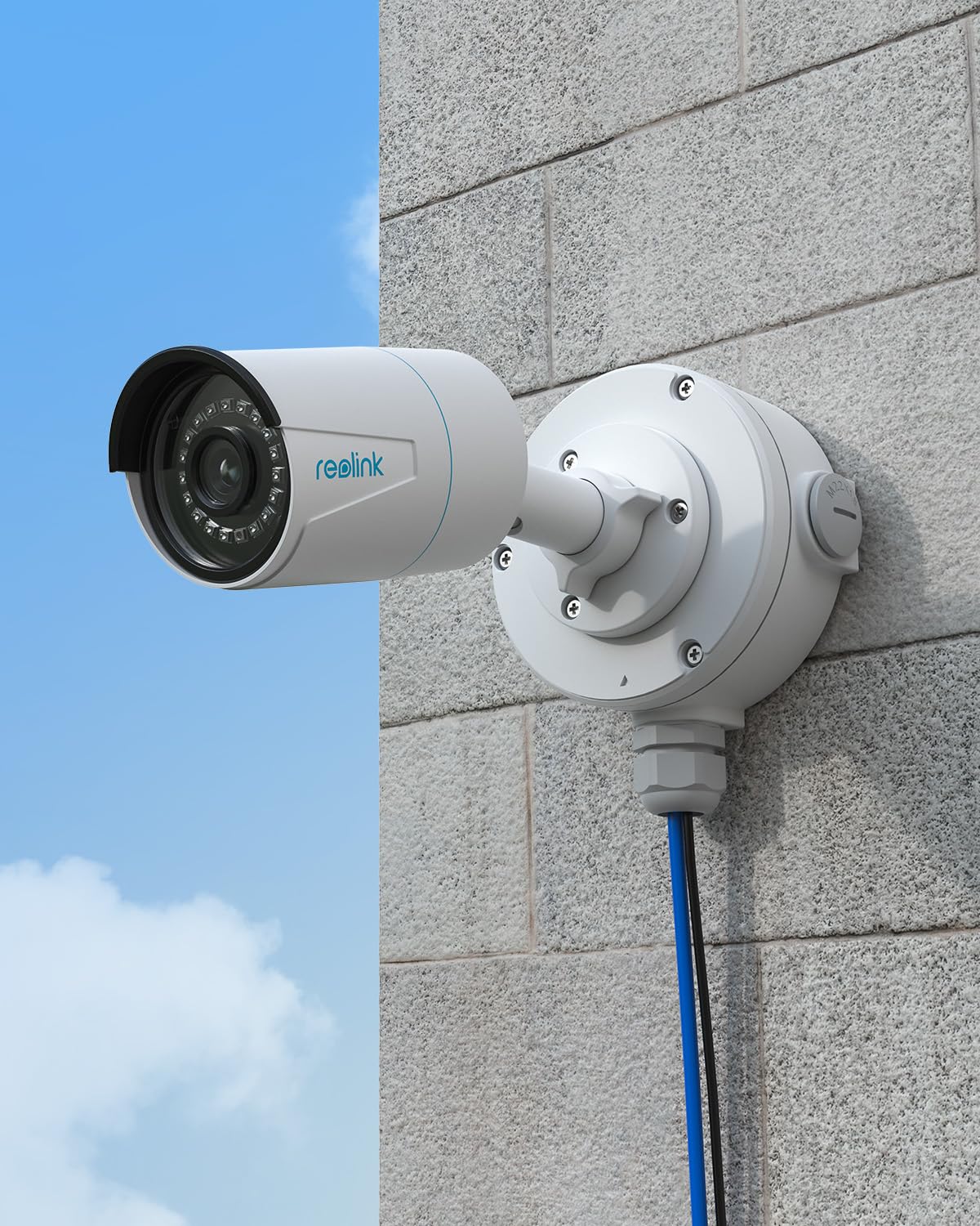
Figure 4: Installed REOLINK Junction Box with Camera
Funtzionamendu-gogoetak
The REOLINK Junction Box B10 is a passive component designed to house and protect camera wiring. Its operation is directly tied to the proper functioning of the connected camera and its power/network supply.
- Ensure all cable glands are securely tightened to prevent water ingress, especially in outdoor installations.
- Avoid over-tightening screws, which could damage the aluminum alloy or the camera's mounting points.
- Periodically inspect the junction box for any signs of wear, damage, or loose connections, particularly after severe weather conditions.
Mantentzea
The REOLINK Junction Box B10 requires minimal maintenance. Regular inspection is recommended to ensure its continued performance and protection of your camera's connections.
- Garbiketa: Garbitu konexio-kutxaren kanpoaldea oihal leun eta lehor batekinamp cloth to remove dust or dirt. Do not use harsh chemicals or abrasive cleaners.
- Ikuskapena: Annually inspect the integrity of the seals and the tightness of all screws, especially if the box is exposed to harsh weather. Check for any signs of corrosion or physical damage.
- Kable-gurutzeak: Ensure cable glands remain tight around the cables to maintain waterproof sealing.
Arazoak konpontzea
Most issues related to the junction box are installation-dependent rather than product defects. If you encounter problems, consider the following:
| Arazoa | Kausa posiblea | Irtenbidea |
|---|---|---|
| Water inside the junction box | Loose cable glands or improperly sealed cover. | Ensure all cable glands are tightened securely around cables. Verify the cover is properly aligned and all screws are tightened to create a watertight seal. Consider applying a bead of silicone sealant around the camera's mounting base if used outdoors, as suggested by user reviews. |
| Camera mounting holes do not align perfectly | Slight manufacturing tolerance variations or incorrect mounting pattern selected. | Carefully align the camera. If slight misalignment occurs, gently apply pressure while tightening screws evenly. Ensure you are using the correct mounting pattern (A, B, C, D series) for your specific camera model. |
| Torlojuak estutzeko zailtasuna | Screws are cross-threaded or holes are misaligned. | Ensure screws are inserted straight and not cross-threaded. If holes are slightly off, try to start all screws loosely before fully tightening them in an alternating pattern. |
Zehaztapenak
| Ezaugarri | Xehetasuna |
|---|---|
| Modelo zenbakia | B10-2 Pack |
| Materiala | Aluminiozko aleazioa |
| Kolorea | Zuria |
| Akabera mota | Anodizatua |
| Neurriak (gutxi gorabehera) | 144 mm (Altuera) x 122 mm (Zabalera) x 45.5 mm (Sakonera) |
| Pisua (gutxi gorabehera) | 1.83 libera (2ko paketearentzat) |
| Bateragarritasuna | REOLINK Bullet Cameras (B400, RLC-510A, RLC-510WA, RLC-810A, RLC-811A, RLC-811WA, RLC-81MA, RLC-81PA, RLC-1210A, Duo 2 PoE, Duo 2 WiFi, CX410) |
| Ingurumenaren Balorazioa | Waterproof (suitable for indoor/outdoor) |

Figure 5: REOLINK Junction Box B10 Dimensions
Bermea eta Laguntza
For warranty information and technical support, please refer to the official REOLINK website or contact REOLINK customer service directly. Keep your purchase receipt as proof of purchase for warranty claims.
REOLINK Official Webgunea: www.reolink.com
Bezeroarentzako laguntza: Refer to the support section on the REOLINK website for contact details, FAQs, and troubleshooting guides.